
16
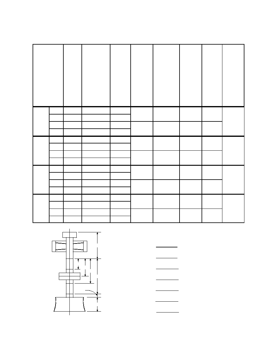
Upper Wear Ring
Thrust Runner
1st Band
2nd Band
Centerline of
Coupling
3rd Band
4th Band
Lower Wear Ring
A
E
B
C
D
G
F
Unit Alignment Worksheet
Column
1
Actual
Reading
Column
2
Mathematical
amount to be
added to
Column 1 to
theoretically
move all wires
an equi-
distance from
center of shaft
Column 3
Total
Column 1
plus
Column 2
Column
4
Difference
N&S
E&W
Column
5
½ Column 4
(Out of Plumb
between top
and bottom
reading)
Column
6
Direction
bottom of
shaft is out
of plumb.
(Direction
of smaller
number in
Column 3)
Column
7
Total
N+S
and
and
E+W
from
Column 3
Column
8
Out of
Roundness
or
inaccuracy
of readings
(N+S)-
(E+W)
(E+W)
Should be
less than
0.002
Fi
rs
t
R
eadi
ng
E
l
evati
evati
o
n
North
0.3445
0.0000
0.3445
0.0000
South
0.1505
0.1940
0.3445
East
0.1710
0.1735
0.3445
0.0000
West
0.2985
0.0460
0.3445
S
e
cond
R
eadi
ng
E
l
evati
evati
o
n
North
0.3425
0.0000
0.3425
0.0035
0.00175
N
0.6885
0.0000
South
0.1520
0.1940
0.3460
East
0.1710
0.1735
0.3445
0.0005
0.00025
W
0.6885
West
0.2980
0.0460
0.3440
Thi
r
d
d
R
eadi
ng
E
l
evati
evati
o
n
North
0.3495
0.0000
0.3495
0.0080
0.0040
N
0.7070
0.0010
South
0.1635
0.1940
0.3575
East
0.1800
0.1735
0.3535
0.0010
0.0005
W
0.7060
West
0.3065
0.0460
0.3525
Fourth
R
eadi
ng
E
l
evati
evati
o
n
North
0.347
0.0000
0.3470
0.0120
0.0060
N
0.706
0.0005
South
0.1650
0.1940
0.3590
East
0.1805
0.1735
0.3540
0.0015
0.00075
W
0.7065
West
0.3065
0.0460
0.3525
A = 170
B = 25
C = 40
D = 55
E = 80
F = 85
G = 25
Figure 14.--Unit alignment worksheet.